|
|
| 
|
|
MIDI
Musical Instrument Digital Interface
Advanced MIDI (Musical Instrument Digital Interface)
MIDI by the Numbers
The "inner workings" of MIDI is relatively easy to
understand once you know the source coding which is employed
into this system. Since computers and computerized devices
process data at the binary level, a standard "code" was
employed to allow the end users to generate messages within
this system, as well as to allow these various devices to use
the same coding between each other. However, binary (or base
2) numbers can be quite large, consisting of ones and zeros to
represent high-level numerical equivalents, whether they are
in decimal (base 10) or any other numerical system. This is
where "exponential notation" comes into play to help solve
this problem. You have the end user on one side of the system
who understands decimal numbers, and on the other side is the
computer device which is quite comfortable with binary.
However, a logical solution to this was already developed way
before MIDI was ever conceived. A form of numerical coding
which was first used with Bendix computers was later adapted
by IBM to form a similar code using the same "base 16" system.
But since there are only ten unique digits in decimal (0 - 9),
alphabetical characters had to be used for a singular digit to
express values from 10 to 15 in decimal. The Bendix system
used the last 6 letters of the alphabet, U V W X Y Z, to
represent these digits, and then IBM changed that to the first
six letters of the alphabet, A B C D E and F to do the same.
This system was named "Hexadecimal" (derived from both Greek
and Latin to mean "six" and "ten" or together, "16").
Let's take a closer look at these numbering systems. In
decimal, we know that our digits are 0 - 9 and that each
column represents a power of ten. With any other base, the
digits allowed are always one less than the base, so in binary
(base 2), we can only use a "1" or a "0" for each digit, and
each column other than the "ones column" represents a power of
two. The "ones" column is actually 2 to the 0 power since we
don't have a power of two. In decimal, we have the ones column
expressing values from 0 to 9, and if we add one we now have a
power of 10, so each column to the left of the ones column
represents a power of ten. We can think of this exponentially
(as in scientific notation) as 100 (ones), 101
(tens), 102 (100s), 103 (1000s), . . .
and so on. In "Hex", we still have the ones column for values
0 - F (decimal 15), but when we add 1 to F we now have a power
of 16 or 10 (Hex), so each column to the left of the ones
column represents a power of 16, or 161, 162,
163, etc. Since the base is larger than both binary
and decimal, we can represent large numbers from either
numbering systems in Hexadecimal with fewer digits, making it
very easy to express these numbers or interpret them for the
end user.
You can also see this by using your Windows calculator and
switching from the "standard mode" to the "scientific mode".
You will see selections for Hex (base 16), Decimal (base 10),
Octal (base 8), and Binary (base 2). Octal (or base 8) was
only used on some select computers, but the other three bases
are more commonly used today. The convenience of Hex is that
if you can count from 0000 to 1111 (in binary), you can easily
translate any large binary number to Hex, using the digits
from 0 and F. (See the table below).
|
Decimal |
Binary |
Hex |
|
0 |
0000 |
0 |
|
1 |
0001 |
1 |
|
2 |
0010 |
2 |
|
3 |
0011 |
3 |
|
4 |
0100 |
4 |
|
5 |
0101 |
5 |
|
6 |
0110 |
6 |
|
7 |
0111 |
7 |
|
8 |
1000 |
8 |
|
9 |
1001 |
9 |
|
10 |
1010 |
A |
|
11 |
1011 |
B |
|
12 |
1100 |
C |
|
13 |
1101 |
D |
|
14 |
1110 |
E |
|
15 |
1111 |
F |
By grouping the binary digits into 4-bit groups, each group
can be represented by a single Hex digit. Thus, a byte of
information consists of 8 bits (or two groups of 4 bits each),
or two Hex digits. For example, the binary number 0111 1111
equals 7F in Hex. The "7" represents the "Most Significant
Bits" (or MSB), and the F represents the "Least Significant
Bits" (or LSB). We refer to half of a byte (4 bits) as a
"nibble", thus "two nibbles to the byte". The value range for
a byte is from 00 to FF, or in binary, 0000 0000 to 1111 1111.
That translates in decimal from 0 to 255 (or 256 possible data
values).
Now all of this is grand for the computer programmer to
use, however Dave Smith (President of Sequential Circuits)
probably understood the potential of using this numerical
system to establish the functionality of the MIDI protocol.
The MSB of a byte would be considered the Status part
of a MIDI message and the LSB could be used to indicate a MIDI
channel with values from 0 to F, or 16 possible MIDI Channels.
Following the Status byte, data byte values would range from 0
- 127 (decimal), 0000 0000 - 0111 1111 (binary), or 00 - 7F
(Hex). For example, a message to trigger a note would be:
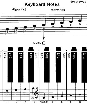
90 3C 40 (in Hex). The "9" is the "Note On Status",
followed by "0" representing the MIDI Channel 1 (or n+1). The
next byte is the note number in hex, 3C which is "Middle C"
(decimal value = 60), and the last byte of the message
represents a key velocity of 40, (decimal value 64), which is
a medium velocity value. The MIDI Specification will explain
these messages in greater detail. To turn that note off, when
the key is released, another "note-on" event is transmitted
but in this case the velocity value is set to "0". Thus,
note-on events can be used to trigger a note on and off using
the same status format, totaling 6 bytes per note, (without
aftertouch values). With aftertouch, in which further pressure
is applied to a key or group of keys, many addtional bytes are
sent to reflect this control value to the receiving device, be
it a MIDI sequencer (recorder), or a MIDI sound generator. And
so, a MIDI sequence containing aftertouch information will be
much larger than a sequence which did not record aftertouch
values. Depending upon the instrument or MIDI controller,
aftertouch can be either "channel aftertouch" in which the
greatest amount of aftertouch affects all notes on one
particular MIDI channel, or "polyphonic aftertouch" in which
each key transmits its own aftertouch value and each notes
responds with each aftertouch control, individually.
The Full Range of "MIDI Notes"
The full "MIDI Note Range" is actually larger than the
88-note piano keyboard, extending above and below it to allow
for octave shifting or pitch bending of MIDI notes up to about
two octaves in either direction, (up or down). Since we have
128 possiblities for our note data, the MIDI spec allows for
notes which are actually beyond the physical scale of some
virtual instrumentation.
MIDI Keyboard Controllers come in various sizes with
varying numbers of notes and octaves. The following chart
shows some of this coverage by comparing the full MIDI note
range to several MIDI keyboard controllers. In this case, I
compared a 4-Octave (49-note) Roland PC-200 MK II MIDI
controller, a 5-Octave (61-note) Roland Juno-106 synth, a
76-note Roland KR-500, and a Technics PR-305, 88-note digital
ensemble piano. The PC-200 can shift its 5-octaves of "C"
range up or down one octave through MIDI at a time. The other
keyboards can transpose in half-steps within a certain range,
up or down, and octave shift through MIDI, as well. I have
arranged the four keyboard controllers in this diagram with
the full MIDI scale so that Middle "C" (MIDI note #60, or C4
which means the 4th MIDI Octave of "C") is vertically aligned.
You can click on the image below for a larger view as an Adobe
Acrobat (.pdf file).
This comparison represents what MIDI notes are transmitted
by playing each keyboard. MIDI-note reception ranges may vary
with each sound-generating keyboard. Simarly, MIDI-note
reception may also vary with each MIDI tone generator in a
MIDI setup, so it's a good idea to explore the MIDI
implementation chart for each device used when sequencing.
Other channel messages include control changes such as
channel volume (MIDI volume), program change (sounds), pitch
bend, modulation, sustain pedal values, panning control,
channel or polyphonic key pressure (aftertouch), and others.
The MIDI data for these controllers generally works in this
way: for continuous controllers (such as MIDI volume, panning
and parameter sliders), the data range is 0 - 7F (Hex) and the
values in-between are considered as each control is varied
continuously. For "on" and "off" switches, such as a sustain
pedal, only the two extreme values are considered, thus 7F(H)
is "On" and 00(H) is "Off" and the in-between values are
ignored. So, if you were to manually insert a sustain pedal CC
value of 7F in a MIDI sequence, the notes on that channel
would sustain until another pedal value of 0 is received. You
could also record the action of a continuous controller or
parameter edit in real-time within a MIDI sequence, and then
look at these values within the sequence to determine their
format and function and then edit them manually.
Also, some controllers, such as pitch bend and aftertouch
require additional bytes of data which makes it a little more
difficult to create manually. However, they do work well when
recorded in real-time when transmitted by the actual MIDI
controllers. A MIDI sequence will require more bytes for a
performance containing aftertouch and pitch bend information
from a MIDI keyboard than a keyboard which does not transmit
these values, especially with polyphonic aftertouch in which
each note transmits its own aftertouch values when its key is
depressed with extra force after having been initially struck.
But these performance controllers add more depth of expression
and realism to a recording with voices such as brass,
woodwinds, strings and synth sounds. You would not expect a
piano track to have either pitch bending or aftertouch
controllers by comparison, even though it might be possible to
record such controllers to affect a piano MIDI track.
Besides channelized messages, MIDI offers channel mode
messages, system common messages (such as a tune request), and
system Real-Time messages which control song-playback
parameters such as "start", "stop" and "continue" for a MIDI
"song", timing clock, reset back to measure 1, etc. System
Exclusive messages allow transmission and reception of bulk
data, parameter changes, and much more. To prevent devices
from translating data which is not intended for them, the use
of manufacturer, model and device ID codes were established
for each company, device and model. You can look up the
specifics for each device as indicated by the MIDI
Implementation Charts which are supplied by each manufacturer.
These charts indicate the details as to what messages are
transmitted and recognized, and other MIDI specifications, and
may express these values in either binary, hex or decimal.
Typical MIDI Scenarios
When MIDI was originally adopted by the industry,
keyboardists were delighted to find that they could connect
two MIDI synthesizers together and trigger both from the
master keyboard (known as MIDI layering). This was quite an
improvement over the earlier control voltage method of note
triggering which often resulted in "stuck notes" and other
undesirable effects. Eventually, the first MIDI sequencers
were introduced and they were typically 2-track recorders with
limited memory capability and functions. But in time, these
stand-alone sequencers became more sophisticated and allowed
the user to mix tracks, edit notes and other data, and perform
a variety of song-composition tasks. The standard MIDI clock
on the sequencer could be synched to a drum machine and either
one device could regulate the timing of the other.
Click
here
for a diagram of some basic MIDI setups for performance and
recording.
Eventually, the synth manufactures developed MIDI sound
modules to add additional sounds for either performance or
recording purposes. As the sound-generation technology became
more sophisticated, the musical realism of a MIDI sequence
greatly improved. Computer sequencing software developed in
time, as well, to allow composers to graphically view and edit
a variety of recorded MIDI events and messages.
Today, computers function as MIDI seqencers, data and voice
librarians for sound modules, keyboards or drum machines, and
advanced digital processing which may include sound
generation, digital sampling, mixing, notation, effects
generation and more. The concept of continuous controller
values can be used to control animation effects and even stage
lighting production. In time, the MIDI protocol has not
changed as much as the various uses for it in the music
industry. The development of alternative MIDI controllers has
enabled other musicians to enjoy the benefits of MIDI, as well
as keyboardists. Several manufactures developed electronic
wind instruments (EWI), MIDI guitars and other types of MIDI
controllers which could now accurately transmit stable MIDI
note messages from non-keyboard controllers to sound
generators for this purpose.
MIDI sound modules or tone generators became
"multi-timbral" devices which could assign various sounds to
individual parts, thus allowing for a complete musical
performance from just one of these devices. The classic
examples of these were the Roland SC-55 "Sound Canvas" which
was small and portable, but offered a complete range of sounds
(including percussion and sound effects) over 16 MIDI
channels. Yamaha offered a similar device starting with the
TG-1 and MU50 series.
It became obvious that a standard for voice assignments
would help unify MIDI sequences so that they would sound
appropriately when played on a different systems. Roland and
other manufacturers agreed upon the Standard MIDI File
convention, (SMF), which assigned the same basic sounds for
conventional program change commands. It also suggested that
drum parts be assigned to channel 10 within this standard,
however the user could still choose to assign additional drum
parts or sounds on other channels. Thus, the observance of
this format was generally recommended for sake of
conventional, but not necessarily an absolute requirement for
all MIDI sequences. The "down side" of this format was a
limited range of 128 "primary tonal instruments" plus drums,
even though there are many other alternate sounds available
for use on various multi-timbral modules and keyboards. The
"plus side" was that if I selected a piano sound with a
program change value of "1" for Part 1 of my MIDI sequence,
then playback on another system would select a similar type of
piano sound for the same part.
Prior to this convention, Roland was generally assigning
drum parts to MIDI Ch. 10, and Yamaha was using Ch. 16
(especially on Clavinovas, DOM-30 "Disk Orchestra" modules,
TG-100 tone generators, and Electone Organs). Other companies
(such as Korg) were assigning drum parts on just about any
channel the user chose. You could quickly tell this when you
heard a piano sound trying to respond to note messages
intended for drums. . . a rather "noisy" scenario. At the very
least, the SMF convention helped to correct this problem and
allow for a more universal system of MIDI recording and
performance for global distribution purposes. Later-on, the
use of "SMF" files for karaoke use was added to the convention
as a "Type-0 SMF" which included embedded lyrics on their own
MIDI track. These were then displayed through video monitors
on playback with the help of a device which decoded these
lyrics and highlights each word as they were played within the
MIDI sequence. SMF MIDI Files without lyrics are known as
"Type-1". If you want to have lyrics displayed on a MIDI
device with a known display address, I will discuss how you
can achieve this in a moment with System Exclusive Messages.
Program Changes
Early synths and modules, such as the Roland JUNO-106 and
others, conveniently had 128 programs (or sounds) to select
for playing or recording through MIDI. These were usually
arranged as two groups (Group A and B) of 64 programs for each
group, and 8 banks with 8 programs for each bank, or 128
sounds in total. When more than 128 sound programs were
included in a keyboard or MIDI sound module, this exceeded the
normal range for a standard program change command within the
00-7F data range. One solution to this problem was to allow
the end user to create a program change map (essentialy, a
memory buffer or array to assign programs from higher banks to
correspond to a basic program change message of 128 possible
numbers). In that scenario, a program change of "1" might call
up a program from the 5th bank, sound number 30, thus two
bytes of data would be stored in the first program change
address to call up this program.
A sound module I recall which had this feature was the
Yamaha TX81Z which had a user-assignable program change map.
Eventually, the MIDI Spec. allowed for a "Bank Select" command
to accompany a program change command to select sounds from
program banks exceeding the standard 128 sounds. For MIDI
sequences which have such commands, they are not considered as
true SMF or General MIDI format since the results may be
different on various tone generators. However, it does allow
the user to specify alternative sounds within the MIDI
sequence for their own use and proper playback. For this
reason, again, General MIDI and Standard MIDI Files are only
considered to be a "convention" and not an "absolute"
requirement to MIDI sequencing in all instances. The end user
can choose to create a SMF MIDI sequence file for distribution
purposes, or create a custom MIDI file for just their own use
for recording or performance.
In either case, it's always a good idea to keep a "MIDI
Track Production Sheet" printout for each MIDI sequence. On
this, you would indicate the programs used on all 16 MIDI
channels, and some setup notes about specific channels or
tracks so that you can recreate the setup at a later date. You
might want to indicate what sound module was used and any
other custom details, such as mixer levels, EQ, effects, etc.
As always, the more documentation, the better!
Dynamic Voice Allocation and Voice Reserve
Many multi-timbral sound modules reserve the most amount of
voices for piano and drum parts to avoid "note-robbing". For
this reason, most MIDI sequences have the piano part recorded
on MIDI Channel 1 (and Ch. 2 for a split-piano performance).
The idea of this is that we don't want to lose piano notes in
favor of a secondary instrument on another channel (which
might happen as you approach the voice-limitation of the sound
module). Voice Priority in the Genral MIDI format is usually
assigned as follows:
MIDI CH. 1 (Piano)
MIDI CH. 10 (Drums)
CH. 2
CH. 3
CH. 4
CH. 5
CH. 6
CH. 7
CH. 8
CH. 9
CH. 11
CH. 12
CH. 13
CH. 14
CH. 15
I usually assign MIDI Channels 1 and 2 for keyboard parts,
Ch. 10 for drums, Ch. 3 for bass, and then build the remainder
of my instrumentation upwards sequentially by channel number
for additional instruments as they are needed (Guitar,
Strings, Brass, Woodwinds, etc.). As you can see, the lower
the channel number, (with the exception of MIDI Ch. 10), the
higher the priority is assigned for those voices. In some
cases you can alter this priority, but in general, it's a good
thing to keep in mind, especially with modules with limited
voice capacities. For SMF sequences with just piano parts, the
convention is usually on Ch. 1 or, Channels 1 and 2 (if the
treble and bass clefs are assigned individual MIDI Channels).
System Exclusive Messages
By definition, System Exclusive messages are intended to be
sent to and from specific MIDI devices. These messages could
be changes in specific parameters, system functions, or even a
complete data dump containing all of the programmable
information for a singular device. The obvious benefits of
this is the ability to store this information on an external
device, such as a personal computer or hard drive, and to
allow for computer software to functions as "data librarians"
and "voice editors". Even the end user can generate such
messages and embed them into a MIDI song sequence, but it
requires just a little knowledge of the MIDI implementation
for that specific device. For this purpose, the manufactures
included the format for these commands in their owners manual,
in addition to the "MIDI Implementation Chart" which briefly
describes which type of messages these devices transmit and
receive.
Some vital components which prevents a device from
interacting with data that is not intended for it are: 1) the
MIDI Manufacturer ID Number, 2) the Model ID, 3) the Device
ID, and 4) model-specific "data hand-shaking." When the MIDI
Specification was first introduced, each MIDI manufacturer was
assigned an official MIDI Manufacturer ID Number upon their
application. This would prevent devices from another company
from responding to data which was intended for another. Some
examples of these are:
|
ID Number |
MIDI
Manufacturer |
|
40H |
KAWAI |
|
41H |
ROLAND
CORP. |
|
42H |
KORG INC. |
|
43H |
YAMAHA
CORP. |
|
44H |
CASIO |
As more companies applied, the ID number expanded into a
three-byte number for assignment. The Model ID number would
exclude the interaction of different devices from the same
manufacturer other than the intended device. Also, the MIDI
Manufacturers Association (MMA) encourages all MIDI
manufacturers to publish their System Exclusive Formats so
that the end user can constructively utilize them. In the case
where two of the exact same devices exist in a MIDI system,
the user could assign a different device ID for each, thus
isolating one device and data set from another. (The default
is usually device number 10H when not changed by the user.)
System Exclusive Message Example
Let's explore a system exclusive command scenario. . . In
this case, I would like to send a Sys-Ex message from my
sequencer to my Yamaha MU50 tone generator to display some
characters on the system's front panel display. The computer
industry has adopted the ASCII standard of assigning data
values for alphanumeric characters. Using just 7 bits for this
data, values from 0-127 (dec) or 00-7F (hex) have been
assigned to each character on the ASCII table. The "extended
ASCII character set" ranges from 128-255 (dec), or 80-FF (hex)
and is used for European accents and special graphical
characters. From the basic character set, the first 32 values
(0-31) are reserved for non-printing functions, while the
remaining byte values 32 (dec) to 127 (dec) are assigned to
the characters we will use in this example. The following
standard ASCII character chart will be used.
|
Dec |
Hex |
Ch. |
Dec |
Hex |
Ch. |
Dec |
Hex |
Ch. |
|
32 |
20 |
Sp. |
64 |
40 |
@ |
96 |
60 |
` |
|
33 |
21 |
! |
65 |
41 |
A |
97 |
61 |
a |
|
34 |
22 |
" |
66 |
42 |
B |
98 |
62 |
b |
|
35 |
23 |
# |
67 |
43 |
C |
99 |
63 |
c |
|
36 |
24 |
$ |
68 |
44 |
D |
100 |
64 |
d |
|
37 |
25 |
% |
69 |
45 |
E |
101 |
65 |
e |
|
38 |
26 |
& |
70 |
46 |
F |
102 |
66 |
f |
|
39 |
27 |
' |
71 |
47 |
G |
103 |
67 |
g |
|
40 |
28 |
( |
72 |
48 |
H |
104 |
68 |
h |
|
41 |
29 |
) |
73 |
49 |
I |
105 |
69 |
i |
|
42 |
2A |
* |
74 |
4A |
J |
106 |
6A |
j |
|
43 |
2B |
+ |
75 |
4B |
K |
107 |
6B |
k |
|
44 |
2C |
, |
76 |
4C |
L |
108 |
6C |
l |
|
45 |
2D |
- |
77 |
4D |
M |
109 |
6D |
m |
|
46 |
2E |
. |
78 |
4E |
N |
110 |
6E |
n |
|
47 |
2F |
/ |
79 |
4F |
O |
111 |
6F |
o |
|
48 |
30 |
0 |
80 |
50 |
P |
112 |
70 |
p |
|
49 |
31 |
1 |
81 |
51 |
Q |
113 |
71 |
q |
|
50 |
32 |
2 |
82 |
52 |
R |
114 |
72 |
r |
|
51 |
33 |
3 |
83 |
53 |
S |
115 |
73 |
s |
|
52 |
34 |
4 |
84 |
54 |
T |
116 |
74 |
t |
|
53 |
35 |
5 |
85 |
55 |
U |
117 |
75 |
u |
|
54 |
36 |
6 |
86 |
56 |
V |
118 |
76 |
v |
|
55 |
37 |
7 |
87 |
57 |
W |
119 |
77 |
w |
|
56 |
38 |
8 |
88 |
58 |
X |
120 |
78 |
x |
|
57 |
39 |
9 |
89 |
59 |
Y |
121 |
79 |
y |
|
58 |
3A |
: |
90 |
5A |
Z |
122 |
7A |
z |
|
59 |
3B |
; |
91 |
5B |
[ |
123 |
7B |
{ |
|
60 |
3C |
< |
92 |
5C |
\ |
124 |
7C |
| |
|
61 |
3D |
= |
93 |
5D |
] |
125 |
7D |
} |
|
62 |
3E |
> |
94 |
5E |
^ |
126 |
7E |
~ |
|
63 |
3F |
? |
95 |
5F |
_ |
127 |
7F |
DEL |
The owners manual tells me that I can send a Sys-Ex message
to the system address: 06 00 00 including ascii values
up to 20(H) (32 bytes of data) and select characters
from 20 - 7F(H) which are those on the previous chart.
The first byte will be the System Exclusive status byte
"F0" (which is not channelized), followed by the
manufacturer MIDI ID code for Yamaha "43" (H), then the
device number "10" (H), model number "4C" (for
the MU50), the base address 06 00 00, the ascii data
bytes, and end with a F7 (a.k.a. EOX or, End Of
Transmission) to indicate the end of the message. The first 16
bytes of data will be the top line on the display and the
remaining 16 will be the bottom line of the character area on
the display. The whole message will look like this:
F0 43 10 4C 06 00 00 20 20 20 20 54 48 49 53 20 49 53 20 20
20 20 20 20 20 20 20 41 20 54 45 53 54 21 20 20 20 20 20 F7
When sent, the screen will display this for about the
duration of a measure at 120 bpm (about 4-5 seconds):
|
_ |
_ |
_ |
_ |
T |
H |
I |
S |
_ |
I |
S |
_ |
_ |
_ |
_ |
_ |
|
_ |
_ |
_ |
_ |
A |
_ |
T |
E |
S |
T |
! |
_ |
_ |
_ |
_ |
_ |
I can also send a single character to a relative address
from the base. For example, the last character element address
on the top line would be at: 06 00 0F.
Another use of the character area would be to insert song
lyrics in ascii to appear in time with the song's melody, thus
creating a sort of karaoke MIDI sequence. I have done this
with the Yamaha MU50, the Roland MT-32 and the Sound Canvas
(Roland SC-55) since the display addresses are listed in the
MIDI implementation sections of the owners manuals.
There is also a bitmapped area on the MU50's display which
I can address by turning bits on or off at address 07 00 00.
Each binary bit represents a pixel block in a dimensional
array of 16 x 16. That one is a little bit more complex since
I have to map out my bits in order to establish the hex data
required. To make that easier, I created a template or
worksheet as a grid where each block represents either an "on"
or "off" bit (a "1" or a "0"). Once I have filled-in the bits
I need, I then just need to convert those binary blocks into
hex bytes for my System Exclusive data string.
Let's examine this process, which is a good exercise in
working with blocks of data within a matrix (or array). The
owners manual tells me that this bitmapped area is 16 column
blocks (or pixels) wide by 16 rows which they have divided
into three sections. The first two sections are 7 pixels wide
by 16 rows, and the last section (the last two columns in the
array) is just two pixels by 16 rows. Each pixel of each row
in the first two sections correspond to the 7 least
siginificant bits of a byte with the most significant bit
being ignored. Thus, the value of that byte can be anywhere
between x000000 and x1111111 (or 00 to 7F (hex). So, the bits
are numbered from right to left as follows:
b6 b5 b4 b3 b2 b1 b0
The last column still requires a full byte to process each row,
but since there are only two pixels to trigger on or off, only
bits b5 and b6 are processed from each byte sent.
|
byte # b6 b5 b4 b3 b2
b1 b0
|
d0 |
1 |
1 |
1 |
1 |
1 |
1 |
1 |
|
d1 |
1 |
1 |
1 |
1 |
1 |
1 |
1 |
|
d2 |
1 |
1 |
1 |
1 |
1 |
1 |
1 |
|
d3 |
1 |
1 |
1 |
1 |
1 |
1 |
1 |
|
d4 |
1 |
1 |
1 |
1 |
1 |
1 |
1 |
|
d5 |
1 |
1 |
1 |
1 |
1 |
1 |
1 |
|
d6 |
1 |
1 |
1 |
1 |
1 |
1 |
1 |
|
d7 |
1 |
1 |
1 |
1 |
1 |
1 |
1 |
|
d8 |
1 |
1 |
1 |
1 |
1 |
1 |
1 |
|
d9 |
1 |
1 |
1 |
1 |
1 |
1 |
1 |
|
d10 |
1 |
1 |
1 |
1 |
1 |
1 |
1 |
|
d11 |
1 |
1 |
1 |
1 |
1 |
1 |
1 |
|
d12 |
1 |
1 |
1 |
1 |
1 |
1 |
1 |
|
d13 |
1 |
1 |
1 |
1 |
1 |
1 |
1 |
|
d14 |
1 |
1 |
1 |
1 |
1 |
1 |
1 |
|
d15 |
1 |
1 |
1 |
1 |
1 |
1 |
1 |
|
byte # b6 b5 b4 b3 b2
b1 b0
|
d16 |
1 |
1 |
1 |
1 |
1 |
1 |
1 |
|
d17 |
1 |
1 |
1 |
1 |
1 |
1 |
1 |
|
d18 |
1 |
1 |
1 |
1 |
1 |
1 |
1 |
|
d19 |
1 |
1 |
1 |
1 |
1 |
1 |
1 |
|
d20 |
1 |
1 |
1 |
1 |
1 |
1 |
1 |
|
d21 |
1 |
1 |
1 |
1 |
1 |
1 |
1 |
|
d22 |
1 |
1 |
1 |
1 |
1 |
1 |
1 |
|
d23 |
1 |
1 |
1 |
1 |
1 |
1 |
1 |
|
d24 |
1 |
1 |
1 |
1 |
1 |
1 |
1 |
|
d25 |
1 |
1 |
1 |
1 |
1 |
1 |
1 |
|
d26 |
1 |
1 |
1 |
1 |
1 |
1 |
1 |
|
d27 |
1 |
1 |
1 |
1 |
1 |
1 |
1 |
|
d28 |
1 |
1 |
1 |
1 |
1 |
1 |
1 |
|
d29 |
1 |
1 |
1 |
1 |
1 |
1 |
1 |
|
d30 |
1 |
1 |
1 |
1 |
1 |
1 |
1 |
|
d31 |
1 |
1 |
1 |
1 |
1 |
1 |
1 |
|
b6 b5
|
d32 |
1 |
1 |
|
d33 |
1 |
1 |
|
d34 |
1 |
1 |
|
d35 |
1 |
1 |
|
d36 |
1 |
1 |
|
d37 |
1 |
1 |
|
d38 |
1 |
1 |
|
d39 |
1 |
1 |
|
d40 |
1 |
1 |
|
d41 |
1 |
1 |
|
d42 |
1 |
1 |
|
d43 |
1 |
1 |
|
d44 |
1 |
1 |
|
d45 |
1 |
1 |
|
d46 |
1 |
1 |
|
d47 |
1 |
1 |
|
(The "byte #" column is just for reference to the data byte
numbers of d0 to d47). With this chart, you can now
graphically see where each bit will either turn on a pixel
with a "1" or turn it off with a "0". The format of the Sys-Ex
message will be:
F0 43 10 46 07 00 00 (48 data bytes - d0 to d47) F7
The accepted values for d0 - d31 will be anything from 00 to 7F,
and the processed values for the last column (d32 - d47) will
be either 00, 20, 40, or 60. 00 will turn off all bits in this
column, 20 will turn on the right pixel and turn off the left,
40 will turn on the left pixel and turn off the right, and 60
will turn on both pixels in this column. In binary these byte
values would be: 00000000, 00100000, 01000000, and 01100000,
and only bits 5 and 6 will be considered by the system.
Checksums And How To Calculate Them
The checksum, (also known as the "Roland Checksum"), is
another method used to prevent the processing of bulk data
which is not "signed" with an appropriate value to confirm the
authenticity of such data. Provided that the ID code, model
code, device ID, and other codes in the header of an exclusive
message are correct, we now have to signify that the address
and data being sent is "authentic" and should be processed by
the receiving device. An example of the basic message format
would be:
H e a d e r -- Address -- Data -- Checksum -- EOX
or,
F0 41 10 42 12 (Address) (data string) Checksum F7
In this example, F0 is the Sys-Ex status type, 41 is the
Roland MIDI Manufacturer ID number, 10 is the device ID
number, 42 is the model number, and 12 is the command code for
data transmission. The address will be a three-byte number
followed by a string of data bytes, then the checksum, and
finally, the F7 or EOX (End Of Transmission) byte. In order to
arrive at the checksum, we only need to be concerned with the
address and the data bytes. In essence, the sum of the
(address + data) is reduced by either divsion or subtraction
with 80 (H) until there is a remainder which is less than 80
(H). The "Two's Complement" of that remainder will be our
checksum. Another way to look at this is that if we were to
consider the remainder ("R") in binary (for ex., 0100 0000),
reverse the bits to make 1011 1111, and then add 1, you would
have 1100 0000. We ignore the most significant bit since that
indicates a number greater than 80, and you are left with 0100
0000, or 40 (H) as your checksum.
It is probably easier just to think of this as: 80 - R =
Checksum. By "Two's Complement", we mean that this a number
which added to the remainder to make "1" in the Most
Siginificant Bit (or, 80). When you send the data, the
receiving device will calculate the checksum according to the
address and data specified in your Sys-Ex message and compare
it against your's. If they match, then the receiving device
will accept and store the data at that address. If they don't
match, then you will get a "checksum error" message and the
Sys-Ex message will be ignored or not processed. This also
works in the sense that an address of 00 00 00 plus 00 data
would require a checksum of 80 (which is not allowed), thus,
"zero address and data means do not process any data." The
only valid data values for a checksum would be from 01 to 7F.
You can use your Windows calculator in the "Scientific Mode"
(in the Hex mode) to calculate your remainder, and then, your
checksum.
Real-Time Parameter Edits
You can use real-time parameter edits to change the nature
of a sound during a MIDI-sequenced performance. This is easily
achieved from a MIDI keyboard or synth which can transmit a
change in any given parameter while recording this
information. I first discovered this on my Roland Juno-106
synth when I moved a parameter slider in real-time while I was
recording. Each movement of the slider was recorded as a new
parameter change event (System Exclusive Message) into the
sequence. After I made this recording, I could then examine
the data in my sequence which would tell me the exact
parameter values recorded, and also allow me to edit these if
I wanted to vary the effect of the sound edit. This process
added another dimension to making music in that I could vary
the nature of the sound being played, besides just triggering
this sound with just key events. It could even be just one
note, held for a long duration, but having a change in a
filter or some other modulation of the sound during the length
of the sustained note.
Pseudo-Automated MIDI Mixing
Many other gradual changes can be recorded into the
sequence. You can record your own MIDI volumes in real-time
for each individual MIDI channel. This is sort of like
extablishing your own "master mix" for each part and is a form
of "Pseudo-Automated Mixing". Instead of mixing volume levels
on a conventional mixer, you are now creating the same effect
within the MIDI sequence itself. You can also record changes
in panning (left to right or vice versa) of individual parts,
rather than doing this manually on the mixer which would
require separate audio channels for each part. By recording
these elements into the MIDI sequence, the output of the
device can then run in stereo on just two audio channels on
your mixer or amplifier, but your automated mixing will remain
just as effective as with conventional mixing.
Connecting MIDI Devices to a Personal Computer
Perhaps you might want to use the MIDI section of your
computer's sound card as a tone generator for MIDI sequences.
Or, you might wish to edit your MIDI keyboard or tone
generators with computer software. These and other
computer-based functions will require a MIDI Interface for
connection with your external MIDI components, such as the
M-Audio MIDISPORT 2x2 USB, (pictured below). This device
features two MIDI IN and MIDI OUT ports and connects to the
Mac or PC with a USB cable. Four LEDs display MIDI activity on
all ports and another gently pulsates to show that it is
properly USB-enabled.
About MIDI
Making Music with MIDI
MIDI Controllers
MIDI Products
MIDI Glossary
MIDI Sequencers

MIDI is a
trademark of MIDI Manufacturers Association Incorporated.
About MIDI -
Making Music with MIDI
- MIDI Controllers -
MIDI Products -
MIDI Glossary
-
MIDI Polyphonic
Expression (MPE)
|
| |
|
